I was a good friend of Allen Wright and know much about the Meter he designed. Rowland Barkley commissioned Allen to design a meter that was more sensitive than the Mark VI that was in vogue at the time. Two of the findings Allen made on examining the Mark IV was that the meter movement was a cheap piece of crap without any bearings in the movement (in an attempt to make it more sensitive by removing bearing friction) and the other was that the voltagea cross the cans when the TA knob was increased could cause burning of the skin and thus leading to less conductivity with the electrodes. Another key was analysing and determining the resonant frequency (or damping) of the meter movement and replicating that with his design.
Allens solution was to reverse the configuration of the "Wheatstone bridge" circuit and use constant voltage with a variable current rather than the other way around as used by the church. This produced a better meter response with greater reliability during high TA conditions. Also his circuit design used voltage regulators that prevented the "drift" that is inherent in the church design and so his meter never needed to be "trimmed". Allen found a local meter movement manufacturer who was able to make a movement that was more sensitive than the Mark VI movement but still retained the bearings and so was more robust.
As far as I know, Rowland owns the intellectual property of the circuit design as it was his commission. I believe that Hank Levan was licensed to produce the meters as well.
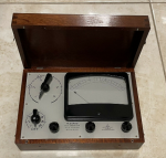
I personally used one of Allens meters for a number of years, first the meter as shown in the picture above and then as a modified Mark VI which had the church meter circuit board replaced with Allens and still provided the electronic TA counter via a separate board.
An issue with any of these designs was the use of tapped NiCad batteries that wear out or leak over time and can be difficult to replace.
I hope this information is useful.
Cheers
Hi Exthetan,
Good to hear from you. If you were a friend of Allen Wright then we probably know each other, unless you were one of the people he put through his OT course in Bondi. In any case, PM me. I have good idea who you might be actually.
")
I've been in contact with Rowland over the past couple of days and he says he may have one at home in Portugal, or maybe in his storage box in Slovenia, but for the next six weeks he's in Brazil. He tells me they used a modified ABC meter movement, and that the company who made them broke the mold and no more movements can be found, which is why it went out of production.
Interesting techy insights there, I look forward to getting hold of one and tracing out the circuit. I very much doubt that skin burning can occur with the Mk VI since the voltage at worst goes to 2.9V or so and at that point current is miniscule (microamps). I have read other claims that the e-meter can cause damage and I find them entirely baseless. But hey, a thetan can become sensitive to anything if they mock it up enough; my niece swears that she can't be in a house with wi-fi because of the radiation.
The voltage regulation will, of course, come at the cost of higher battery usage.
Hank Levin was, I believe, getting the same Excalibur meter as shown above, but with the Alphatronics nameplate. He went on to make his own meter, which seems to be an improvement of the original Allen Wright design, auto-centering being one example. Hank is sadly no longer with us according to his website.
I have no issue with replacing batteries and have just done my MK V, Mk VI and Mk Super VII in the past month. They have all been unused for many years, but now there is a need for them. My Mk VI actually uses 6 x AAA NiMH cells, which is what was fitted when I bought it.
Cheers,
Haiqu


 . I haven’t PM’d anyone here for ages and stupid me cant seem to find the correct button to push. Perhaps you could remind me how. If you live local you would be welcome to collect my emeter for free on an as-is basis. It has not been used for 20yrs and so may need some rejuvenation but sounds like you have the skills to do that. If that interests you then PM me.